C16 Project - Introduction
After my first attempt to build a computer based on 65C816 cpu (MB01-65C816/65C02 Computer), i decided a revision of this
project, learning lessons from some design issues. This second attempt is again based in one "backplane" structure bacause i re-use some boards designed in first project
(CPU board, static RAM boards and video board). Some motivations for this new project:
- First of all the backplane in first project was too big, and placing a lot of i/o devices there was a design error. The new backplane is fully passive (except
for the power control), and then more small. More, the main bus driven by cpu board is inter-mixed with i/o bus, and i no like this feature.
- In first project i used a MOS8563 chip on-board for video control, but after i build the RGB board that can drive a standard VGA monitor, this chip is useless.
Of course is a very nice chip but it dot clock is limited and cannot be able to drive a VGA monitor. Basis on my experiments, the max. clock it accept is about 20MHz,
and i was able in the past to drive a very older multy-sinc monitor, but this is impossible with modern standard VGA monitor (maybe an internal modification to allow an horizontal scan frequency of 16Khz?).
- In first project i put on-board two ata port working in "PIO Mode", but performances was very unsatisfctory. Read/Write 8 bytes at time in PIO mode is slow, so i built an experimental board
( ATA/DMA/FDC Board) as "replacement" for the original FDC board, that use a dma chip for transfer data and take advantage of
16 bit transfer on ata port. Now that is possible to use dma chip for both fast transfers (fdc & ata), ata ports on board are useless, and useless too is the additional FDC bord i
built in first project.
- The serial board, based on 65C52 chip, work fine and this chip is very nice (don't suffer of some issues of the 65C51 chip), but really two serial port are useless. More, the baud-rate is limited
at 57,600 bps max. if this chip is intended to be handled in an interrupt driven environment. I have 65C52 chip targeted for 3MHz bus so requires to use at least
one delay cicle if CPU is clocked at 4MHz. As experiment board i built in the past a board bsed about the standard uart 16C550 with 16 fifo, and thi chip work very fine.
It have a nice vectorized interrupt structure that can make very fast the response and the handling of line errors, and the fifo allow easy to use high baude-rte
(115,200 bps) even in an interrupt driven environment, so definitely i decided to use this chip for serial port.
- Others minor issues are related to the control of power supply for implement a software "shutdown", and some useless control lines as those used for put delay cicles
when accssing some chips, feature that really don't need.
Now that i have in hands the new boards for build this new computer, i can start the realization. These new boards are:
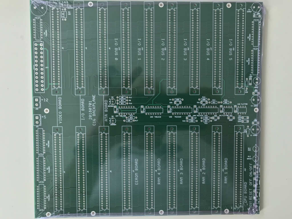
- A new backplane capable of accept 3 large boards (RGB board, main I/O bord, DMA board), and 6 standard eurocard boards (CPU board, four RAM board, ROM emulator board), plus six eurocard boards
on i/o bus. Follow picture of this new backplane board (upopulated).
On left side the power connector for a standard ATX-power supply, 3 double-connectors for insert 3 large boards; on top follow 6 connectors for i/o bus. On bottom follow 6 connectors for main cpu bus.
In this board i put terminator (shottky barrier diode bus-termintor array) and the circuit delegated to control the power on/off and the main reset.
-
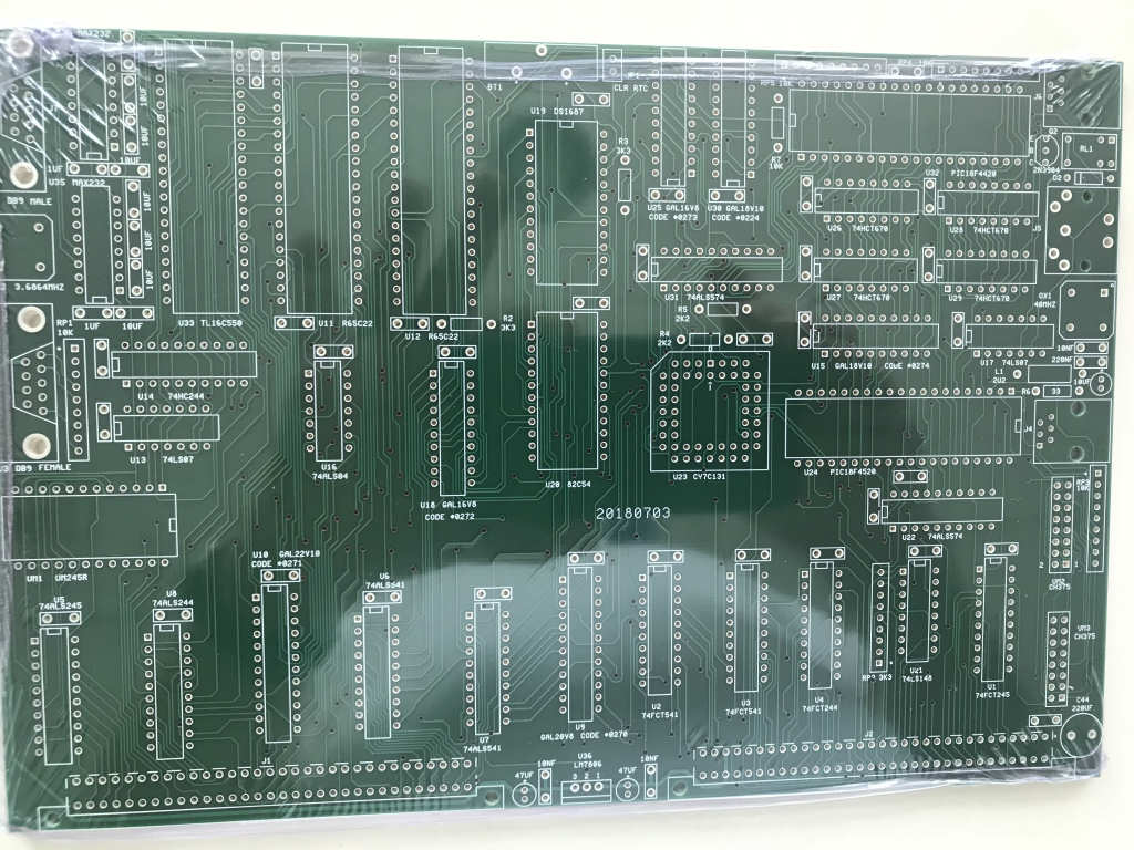
A main i/o board, with rtc, serial port, two 65C22, timer 82C54 (for long time pulses), ps/2 keyboard controller, keyboard & mouse usb controller, and the I/O bus driver
(the main cpu bus is isolated and routed into i/o bus), an additional port for a TI bus (as in texas TI74). Follow picture of this unpopulated board.
On this board installed a slave usb module (UM245R) too intended to be used as debug port connected to PC.
-
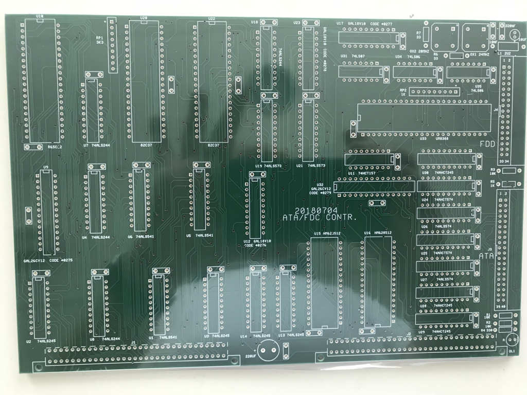
A new DMA board with one fdc port (for connect 2 drive), and one ata port, with 1 Mb of buffer. Follow picture of this unpopulated board.
-
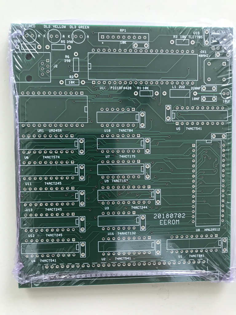
A ROM emulator board for a fast transfer firmware from usb port of PC. Follow picture of this unpopulated board.
C16 Summry Features (initial configuration)
- CPU: 65C816 clocked at 4MHz
- RAM: 16Mb static ram plus 1Mb for dma buffer (switchable on/off)
- FLASH: 512Kb programmable "in-circuit"
- 512Kb ROM emulator loadable by USB
- PS/2 port for keyboard
- USB port for keyboard & mouse
- Serial port RS232 based on standard PC uart
- Floppy disk port working either in PIO mode or DMA mode
- ATA port working either in PIO mode or DMA mode
- RTC with non-volatile ram
- T.I. bus port (formerly: IPB) that can work as "pheripheral device"
- 2 x USB port for external "key" memory
- IEEE488 port configurable either as "controller" or as "device"
- Serial Bus "Commodore style" (formerly: IEC) configurble either as "controller" or as "device"
- Parallel port for printer or others devices
- USB slave port for PC connection (example: debug port)
- Video RGB (text mode only) with VGA 640 x 480 compatible output
- Four I/O free slot for future expansions


